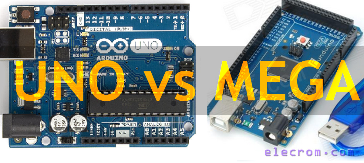
Arduino Zero has 20 digital I / O pins (10 of which can be used as PWM output.). Unlike Uno, Zero can only work with a 3.3 V input supply. You can use it in your IoT projects, wearable technologies and robotics projects. The placement of these pins is as follows: Arduino micro pwm pinoutĪrduino Zero is an advanced version of Arduino Uno. Arduino Micro’s pwm pins are ģ, 5, 6, 8, 10, 11 and 13 pins. It can also be placed on the breadboard easily.The board has 7 pwm channels. It can be programmed with USB cable or RS232-TTL converter. It also has a 16 MHz oscillator, 1 micro USB port, 1 ICSP connection ‘header’ and a RESET button. The board has 54 digital input/output pins (of which 14 can. Arduino Micro has 20 digital I / O pins (7 of which can be used as PWM output, 12 of which can be used as Analog signal input). The A000067 is an Arduino Mega2560 Rev3 development board based on ATmega2560 microcontroller. Arduino Micro Pwm PinoutĪrduino micro is using ATmega32U4 processor. In Arduino Leonardo pwm pinouts are 3, 5, 6, 9, 10,11 and 13. It has 20 digital input / output pins (7 of which can be used as PWM output, 12 of which can be used as analog input), 16Mhz crystal, micro usb socket, power socket, ICSP connector and reset button. Arduino Leonardo Pwm PinoutĪrduino Leonardo It is an Atmega32u4 based microcontroller board. In Arduino Nano, PWM pins are 3, 5, 6, 9, 10 and 11.

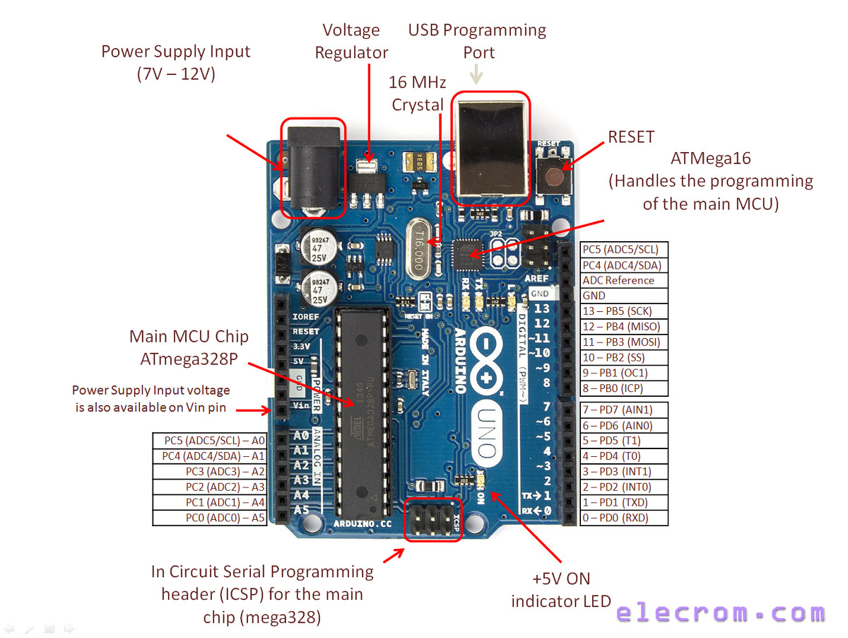
The frequency of the PWM signal on pins 5 and 6 will be about 980Hz and 490Hz on other pins. Another pin is not associated & it is kept for upcoming purposes. One pin is the IOREF that permit the shields to adjust the voltage offered from the Arduino board. Additionally, there are two latest pins located near the RST pin. In Arduino Uno, PWM pins are 3, 5, 6, 9, 10 and 11. The SCL & SDA pins of Mega 2560 R3 board connects to beside the AREF pin. Arduino Uno Pwm Pinout ARDUİNO PWM PINOUT

In this article, we will examine the official arduino platforms. There can be many arduino except Arduino’s official products. Arduino Pwm PinoutĪrduino is an open source project.

The faster the switching is done, the stronger the signal transmitted by PWM. This control is achieved by switching completely. In addition to the purpose of making the signal information suitable for transmission, it also aims to provide power control and support special circuits such as electric machines, solar cell chargers. In its simplest form, it can be described as a signal modulation technique. Pulse Width Modulation is a technique used in special application areas such as Arduino or electrical machines as well as electronic circuits, such as signal processing or signal transfer.


 0 kommentar(er)
